TIMING MAPS
This page will explain our software including:
- Timing steps and how they work
- Fall back RPM
- Rpm limits and how to adjust
- Timing map navigation
- Timing map selection using VOES, MAP sensors, and rotary switches
- Saturation (dwell) -vs- RPM
Timing Steps
Timing must match rpm for maximum efficiency.
As rpm or load changes, the spark must occur earlier or later in the power cycle to allow maximum cylinder pressure at the correct crank pin angle. Our software allows up to 10 steps where timing can be increased or decreased. Take a look at how this works...
As rpm or load changes, the spark must occur earlier or later in the power cycle to allow maximum cylinder pressure at the correct crank pin angle. Our software allows up to 10 steps where timing can be increased or decreased. Take a look at how this works...
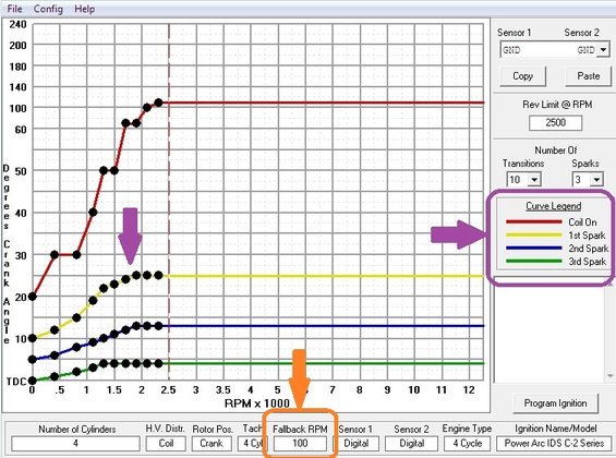
Spark curves:
- Yellow line represents first spark
- Blue line represents second spark
- Green line represents third spark
- Red line represents the coil saturation
Each black dot is a transition point where the timing changes. As rpm increases, timing changes according to the "map". There are four maps saved in your ignition.
Using a transmission on motorcycles or cars, there is opportunity to reduce load on the engine so we can get away with more timing. On pulling tractors the engine rpm does not move much, but the load greatly increases. This requires some unique "outside the box" thinking if you are new to pulling.
As the load comes up and rpm drops, we slowly step back timing. Why does this work so well? As load increases, the piston must work harder to push the piston down. That increase in efficiency also increases the speed at which fuel burns. So as load goes up, timing advance must go down. It is a fine balance.
This is a critical bit of information if you want a reliable and powerful engine.
Fallback RPM
Fall back rpm describes the "step" that occurs when rpm is coming down. On high rpm engines we set it farther apart to keep the engine running smooth. When dealing with low rpm engines we set it close together to make gentle steps in timing. If you wish to "stack" the dots close together, a small fall back is required. We set the fall back rpm before the ignition is shipped to you.
RPM Limits
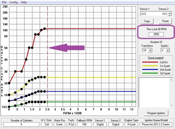
There are two methods of setting the rpm limit on a map. First is to type a value in the rpm limit box on the right side of the screen. Once a value is added it can be modified by over writing or selecting the dashed red line with your mouse and dragging it to the rpm of your choice. If you wish to remove the rpm limit, simply delete the value. Do not use a zero (0) in the box!
The rev limit cannot be less than the rpm of the highest transition point (black dot).
The rev limit cannot be less than the rpm of the highest transition point (black dot).
Timing Navigation & Map Selection
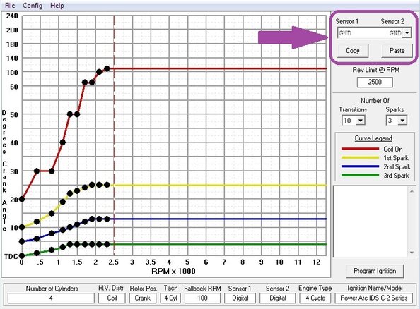
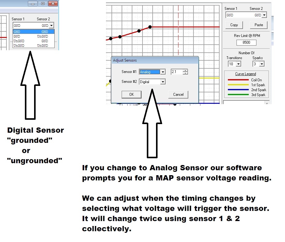
There are four (4) maps saved in the ignition. You select between them by grounding or ungrounding the two sensor leads coming from the ignition module. To view or modify the maps simply select the map options in the upper right corner of the screen.
Once you have selected a map, you can use the scroll button of your mouse to quickly move between the four maps. Each timing map is completely independent. This is how we change timing or rpm limits, even while operating the engine.
**We always designate the first map (both sensors grounded) as map #1, and prefer this map always has the most timing advance. The reason involves safety. If the ground lead(s) break or become disconnected, the ignition is going to jump to map #4 (both sensors ungrounded). If this map has the most aggressive timing it might damage the engine before you realize what happened.
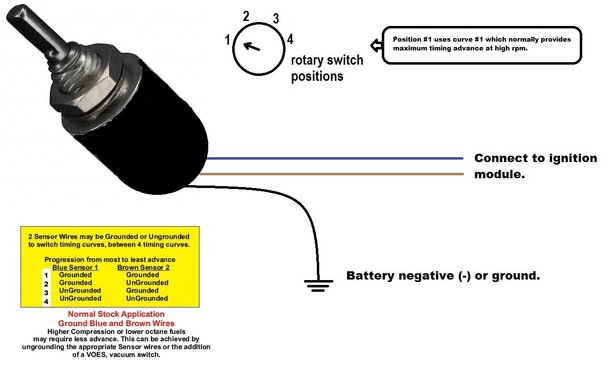
How can you choose which map your engine is using?
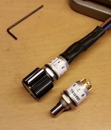
Any means to ground/unground the sensor wires can be used. Simple on-off toggle switches, VOES (vacuum operated) switches, MAP (electronic vacuum switch), rotary switch, or boost sensor can used to control the maps.
Once you have selected a map, you can use the scroll button of your mouse to quickly move between the four maps. Each timing map is completely independent. This is how we change timing or rpm limits, even while operating the engine.
**We always designate the first map (both sensors grounded) as map #1, and prefer this map always has the most timing advance. The reason involves safety. If the ground lead(s) break or become disconnected, the ignition is going to jump to map #4 (both sensors ungrounded). If this map has the most aggressive timing it might damage the engine before you realize what happened.
How can you choose which map your engine is using?
Any means to ground/unground the sensor wires can be used. Simple on-off toggle switches, VOES (vacuum operated) switches, MAP (electronic vacuum switch), rotary switch, or boost sensor can used to control the maps.
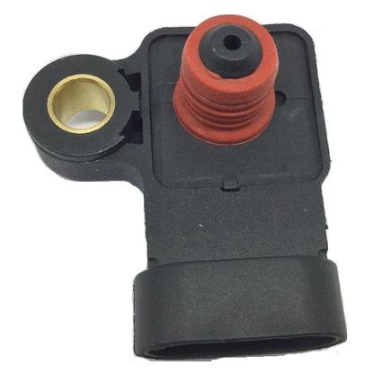
MAP sensors are perhaps the ultimate means to change timing because it is precise and consistent. It does require a bit of home work on your part before it can be used.
- First, you must take vacuum readings to determine what the appropriate level is before changing maps. The goal is to change maps and lower timing, but only when the load is high enough to require it.
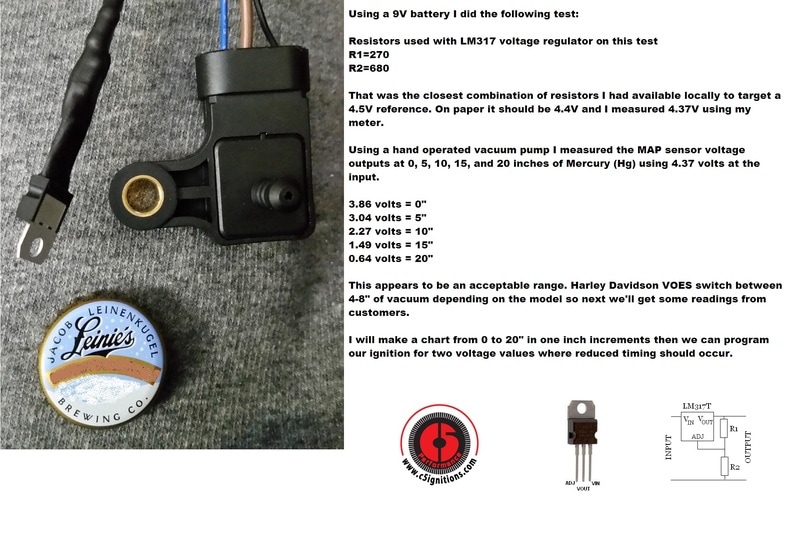
- Take your readings and use a voltage reference chart to find the correct voltage output
- Change the sensor type from digital (on/off) to analog (looks for a specific voltage)
- Type in the appropriate voltage for each sensor.
- Program the new maps (don't forget to change all four) into your ignition.
Saturation Map
Saturation (or dwell) is the "time" a coil is turned on so it can generate high voltage.
Our coils are custom built to offer multiple sparks and are extremely sensitive to saturation (dwell) because of their exceptional efficiency.
For that reason, we use rpm based variable saturation to keep the coils from over heating. The red line on the software represents the point at which the coil is turned on.
Please do not change saturation without consulting us first. There is usually no reason to change it and doing so is dangerous unless you have experience.
Using excessive saturation can cause overheating and failure of the coil and is not covered under warranty. Because the rise rate is extreme, you should leave this to the experts.
Programming Software
Now that you have a basic understanding of the software, here are two options.
Version 3 is an older program without limits on coil saturation. Because the timing transition "dots" are smaller, it works good for very low rpm vehicles such as tractors. Caution must be used or you can damage the coils and we recommend you contact us for training before using this version.
Version 4 is our newer software and is best for motorcycles and high rpm applications. Based on the coil you choose, it can help prevent you from using excessive coil saturation that can damage or destroy the coils.
Training Videos
Downloading Software to your Windows based Computer
Software Training